
Press Brakes
Press Brake Mistakes: 17 Bending Problems and Symptoms and Their Solutions


If you’ve ever had a press brake throw off your bend angle or leave a part just slightly out of spec, you know how fast small problems can turn into big ones. These machines aren’t just hunks of metal, they’re the heartbeat of your shop.
Whether you’re bending flanges for HVAC ducting or forming brackets from stainless, everything depends on clean force, sharp precision, and smooth movement. But even the best hydraulic or CNC system can wear down over time.
You’ll hear it before you see it, vibrations, strange noises, maybe some drift in the back gauge or inconsistent pressure. Sometimes it’s oil leaks, sometimes it’s a tiny alignment issue that throws off your whole batch.
The point is, these are your early warnings. If you catch them early, you stay ahead of downtime, waste, and rework.
So how do we make sure your press brake keeps performing like it should? In this article, we’ll focus on practical maintenance routines, common failure points, and smart troubleshooting habits that can save you time, money, and frustration.
What are the Most Common Press Brake Bending Mistakes and How to Fix Them?

Bending problems like inconsistent bend angles, springback, material cracking, and surface damage are some of the most common press brake mistakes you’ll encounter during fabrication. These issues often arise from overlooked causes such as improper tooling alignment, inaccurate control system settings, or excessive wear on machine components.
If left uncorrected, even minor bending errors can cascade into part rejection, tooling damage, or safety risks.
Being familiar with the role of a press brake in the metal forming process helps explain why accuracy is so critical. As a key sheet metal machine, the press brake shapes material into functional components by applying controlled force to achieve a specific bend radius and angle.
To perform reliably, the equipment depends on correct settings, clean tooling surfaces, consistent material thickness, and a precise back gauge position.
By learning to identify faults early, such as ram drift, die deflection, or stress concentration near bends, you can take targeted corrective actions. Whether you’re adjusting return pressure, inspecting a hydraulic cylinder for oil leaks, or recalibrating angle sensors, the goal is to prevent mistakes before they reduce production quality.
Inconsistent Bending Angles
Inconsistent bend angles are a leading cause of rework in the bending process. You’ll often notice this issue when final parts deviate from the intended design, creating variations in bend precision and dimensional accuracy. The root causes typically include irregular material thickness, worn tooling, and back gauge misalignment.
To fix this, begin by inspecting the die shoulder for wear. If the shoulder shows signs of erosion exceeding 0.1 mm, it’s likely introducing angular deviation. Next, check for inconsistent material placement and confirm that the material thickness is within tolerance across the workpiece.
Back gauge alignment should also be verified, mispositioned fingers can cause angular variation along the bend line.
You should calibrate angle sensors every 40 operating hours and use digital fixture blocks to maintain repeatability within ±0.5°.
Always perform a quick check: measure the bend angle at both ends and the mid-span of your first part. If the angle varies by more than 1°, investigate for bed deflection or ram misalignment.
Springback Effect
Springback is a common and predictable effect that occurs during air bending when the material attempts to return to its original shape after the load is removed. You’ll usually see this with high-strength metals or parts formed with a wide V-die, where the resulting bend angle differs from the programmed value.
The amount of springback varies based on material properties. For example, 304 and 316 stainless steel typically exhibit springback in the range of 6–8°, while 6061-T6 aluminum averages just 2–3°. To compensate, overbending and bottom bending are widely used techniques.
Overbending forces the material slightly past the desired angle, allowing it to spring back into spec. Bottom bending minimizes springback by pressing the sheet firmly against the die, reducing elastic recovery.
You can also reduce springback by decreasing the V-die width-to-thickness ratio.
Lowering it from 12:1 to 8:1 has been shown to cut springback by up to 40%. In more advanced setups, finite element analysis (FEA) simulation software can predict springback to within ±1°, enabling preemptive adjustments without wasting material.
Cracking or Tearing of Workpiece
Cracking or tearing during bending usually stem from three main causes: material brittleness, an excessively tight bend radius, or using the wrong die size. When the bend radius is smaller than the material can tolerate, stress concentration increases and weakens the structure, especially in high-strength metals.
To avoid cracking, make sure your inside bend radius is at least equal to the material thickness—this is especially important when working with high-strength low-alloy (HSLA) steels.
If the ambient temperature is below 10 °C, preheat the material to 150 °C to improve ductility. This small change can help prevent micro-fractures at the bend.
You should also use polished punches with a surface roughness of Ra ≤ 0.4 µm. This minimizes surface friction and removes micro-notches that act as crack initiation points.
Selecting a properly sized V-die for the material thickness and bend angle, and maintaining clean, defect-free tooling surfaces are essential for long-term press brake performance and part quality.
Wrinkling, Bowing, or Twisting
When you see wrinkling, bowing, or twisting in your finished parts, poor material support and excessive tonnage are likely to blame. These bending problems not only affect the shape of the workpiece but also indicate possible system misalignments in the press brake machine.
To prevent twisting, start by checking your gib clearances. If they exceed 0.008 inches, the ram may not be tracking evenly across the bed, leading to deformation. Re-shimming or resurfacing the guide rails can help reestablish parallel movement.
For bowing, it’s essential to support long blanks with anti-sag arms—especially if the blank is longer than four times its material width. Without this support, gravity and bending force can distort the part’s flatness.
Properly distributing the bending force across the die length ensures that the tonnage is controlled and consistent.
Uneven ram pressure, often caused by misaligned hydraulic cylinders or pressure control valve issues, can intensify part warpage. Always verify that your setup matches your sheet metal’s dimensions and properties.
Surface Damage and Die Marks
Surface damage is a frequent issue in press brake operations, especially when forming sensitive finishes like brushed aluminum. These marks often result from contaminated tooling surfaces, incorrect die clearances, or debris such as dust or oil in the bending zone.
Over time, these imperfections lead to wasted parts, reduced quality, and higher rework rates.
One of the best ways to prevent damage is by cleaning your dies before every setup. Even minor oil leaks or metal particles can imprint defects on the workpiece. Data shows that up to 5% of rework in sheet metal fabrication is linked to overlooked contamination or die damage.
You should also consider using UHMW-PE (ultra-high molecular weight polyethylene) film inserts, at 0.25 mm thickness, they are ideal for protecting soft metals without affecting the bend radius or force requirements.
If you notice edge rounding or deep marks, check your die clearance. When the opening exceeds 15% of the punch tip radius, it can cause excessive deformation. Re-honing or replacing the dies will restore precision and reduce repeat errors.
Tooling Misalignment
When the punch and die aren’t centered along the machine’s bed, it can lead to inconsistent bend angles, uneven stress distribution, and damage to both the workpiece and the tooling surfaces. You might also notice irregular flange width or deflection during the return stroke, especially under higher tonnage loads.
To correct this, begin with a full tooling alignment check. Use a laser line reference system to verify that the punch-to-die centerline stays within a tolerance of ≤ 0.05 mm across the full bed length. Any deviation can lead to angle distortion and uneven material flow.
Also, monitor for die deflection under load, if it exceeds 0.3 mm, your tooling may be too soft. Upgrading to 42 HRC hardened steel dies helps maintain shape and force consistency during the bending process.
Back Gauge Inaccuracy
Back gauge inaccuracy can introduce bending problems that affect the final shape, particularly flange length and bend angle. When your workpiece consistently shows variation in position or dimensions, it’s often due to mechanical wear or a control system drift affecting the back gauge.
Symptoms like inconsistent flange width or part misalignment typically point to issues with lead-screw wear or loose belt tension. If you notice average drift beyond ±0.15 mm over 500 cycles, it’s time to recalibrate the axis and inspect the drive components.
Worn bronze nuts should be replaced to restore gauge repeatability. Also, measure X-axis belt deflection—if it’s greater than 3 mm under a 10 N load, re-tension it to meet OEM specifications.
Fixing back gauge inaccuracy improves consistency across parts and extends the press brake machine’s service life. Accurate material placement and smooth gauge movement are vital for maintaining bending efficiency, especially in high-throughput production runs.
Excessive Noise or Vibrations
Unusual noise or vibration in a press brake system often signals deeper mechanical or hydraulic issues that need immediate attention. While some operational hum is normal, certain sounds, like sharp impacts or high-pitched whines, are early indicators of problems within the hydraulic system or motor assemblies.
For example, a distinct “bang” at bottom dead center may indicate a lag in the pressure control valve. In this case, check the timing of the proportional valve; it should respond in under 80 milliseconds.
A continuous noise level above 85 dB typically points to motor bearing wear. If left unchecked, this could lead to motor failure before the end of its L10 life rating.
To maintain system performance and safety, you should schedule a shutdown for diagnostic evaluation when noise levels exceed expected ranges. Proper lubrication, oil level maintenance, and inspection of the filling valve and guide rail assembly are part of this process.
Material Slippage During Bending
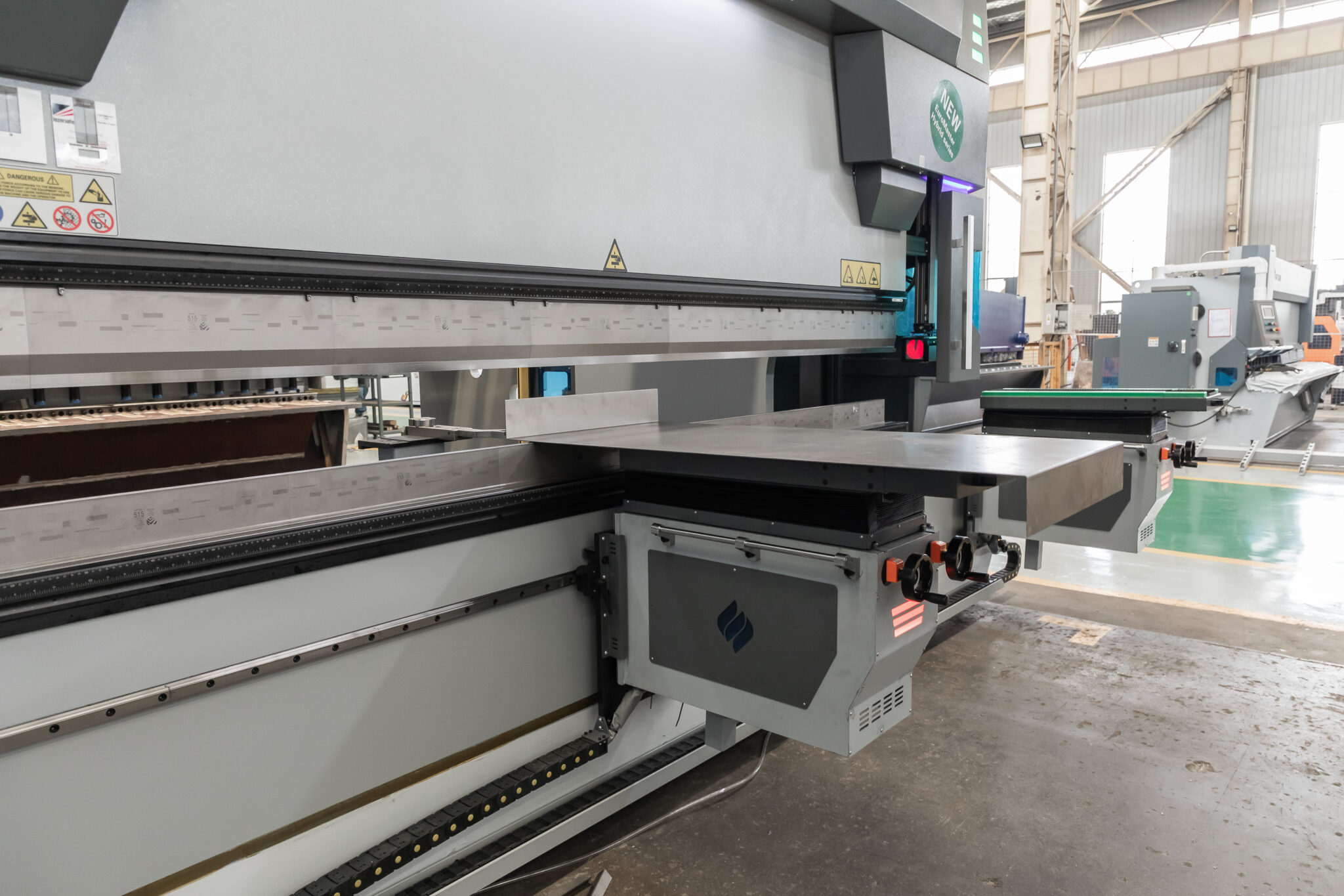
Material slippage occurs when the blank loses grip against the back gauge or clamping fixtures, especially during the downstroke of the press brake ram.
The main causes typically include insufficient clamping force, oily or contaminated sheet surfaces, and worn back gauge fingers. Each of these factors reduces friction between the material and support points, allowing unintended movement during the bend.
To fix this, you should first ensure all sheet metal surfaces are clean and dry—hydraulic oil mist, dust, or machining residue increases the risk of movement. Then apply anti-slip rubberized pads to the gauge fingers and increase clamping pressure by 10–15%, especially when working with smoother metals or lighter gauge parts.
These simple adjustments maintain precise material placement and reduce production errors. Addressing slippage early prevents tooling alignment issues and protects the quality of your press brake operations.
Over-bending or Under-bending
ou may notice that parts consistently overshoot or fall short of the programmed angles, especially when switching between materials or varying die widths.
Under-bending frequently occurs when the die opening exceeds 10 times the material thickness. This mismatch reduces forming pressure at the bend point, leading to flatter angles. In contrast, over-bending is often the result of incorrect material assumptions or overcompensation for springback. Either issue can distort part dimensions and create inconsistencies in your production line.
To maintain precision, calibrate the machine every 1,000 operating hours. This includes checking the angle correction system and updating the CNC database with real-world compensation values.
Most control systems allow for ±1° programmable angle correction, helping you fine-tune results without manual intervention. When properly set, your press brake will deliver consistent results even with small variations in material thickness or tool wear.
Edge Rounding and Die Marks
Edge rounding and die marks are typically caused by excessive die clearance or a worn punch tip, both of which distort the material instead of forming it cleanly along the desired bend radius.
When the die opening is too wide or the punch nose radius has grown beyond 0.3 mm due to wear, the force distribution during bending becomes uneven. This results in rounded edges or visible marks along the bend line, especially noticeable on aluminum or pre-finished metals.
These imperfections not only impact surface quality but also introduce small dimensional errors and stress points that affect the part’s performance over time.
To prevent this, you should regularly re-grind punch tips and polish die shoulders to a mirror finish.
Flange Width Variation
Flange width variation is a subtle yet impactful bending problem that often results in misaligned assemblies or failed fits during final product installation. If you’re noticing dimensional inconsistencies, the likely cause is a mis-positioned back gauge. Even a small deviation during setup can affect bend angle consistency and part symmetry.
Variation greater than ±0.3 mm typically indicates issues with zero-return calibration or probe repeatability. These control system faults are easy to miss during routine operation but have a cumulative effect on finished part accuracy. To check alignment, always verify that the gauge returns to its original position and that the probe engages evenly across all material thicknesses.
For precision adjustments, use the formula:
Flange error = tan θ × back-gauge error
This equation allows you to predict dimensional deviation based on angular discrepancy and gauge offset.
Material Deformation or Thinning
Material thinning during the bending process is a common issue, especially when forming high-strength steels or thinner sheet metal parts. If left unchecked, thinning can compromise the structural integrity of the workpiece, reducing its load-bearing capacity and shortening service life.
One of the primary causes is using a V-die opening that is too narrow relative to the material thickness. When the V-opening falls below 6× the thickness, the bend radius becomes too tight, concentrating force at the inner bend. High-strength steels can thin up to 12% in these conditions. This leads to problems such as cracking, surface distortion, or excessive deflection during the return stroke.
To avoid deformation, choose larger V-dies or switch to bottom bending for better material support. Always refer to the material spec to determine allowable thinning limits.
What Causes Ram Motion Issues During Press Brake Operation?
Ram motion issues in a press brake machine can arise from both mechanical and hydraulic causes. These problems directly affect the control system’s ability to maintain precise movement during descent, dwell, and return phases. When the ram fails to move smoothly or predictably, you’ll often see inconsistent bend angles, material deformation, or premature wear on tooling surfaces.
Common causes include improper filling valve operation, low hydraulic oil levels, or feedback delays in the pressure control valve. Worn guide rails or uneven cylinder response across the bed can introduce misalignment, especially under asymmetric load conditions. Excessive return pressure or unstable air bubbles in the hydraulic oil can lead to jerky motion or vibration.
You should routinely inspect the ram movement path and monitor hydraulic system pressure during the bending cycle.
Look for noise, irregular descent speed, or delayed return stroke, all of which may signal leakage, valve timing errors, or worn hydraulic cylinders. Proactive maintenance of the cooling system, oil filtration, and lubrication points will help reduce motion-related failures.
Problems During Rapid Descent
During the rapid descent phase of a press brake operation, the ram must lower quickly and smoothly to initiate bending. Any disruption here, like hesitation, jittering, or loud impact, can signal deeper issues in the hydraulic system, control logic, or motion components. These problems directly affect bend angle accuracy, increase tooling wear, and slow down production.
Rapid descent depends on a balanced combination of servo commands, hydraulic oil pressure, and correctly functioning filling valves. If one element falls out of sync, the ram may not reach the right position or speed, which disrupts part consistency and increases stress concentration at the bend line. Inconsistent descent is also linked to tight guide rail clearances, causing physical resistance and irregular movement.
Ram Does Not Move Quickly or at All
If your press brake’s ram doesn’t move quickly, or fails to descend at all, it usually points to electrical or valve-related issues. First, check the control system for error messages or loss of signal. The servo proportional valve should receive a clear voltage input between 0 and 10 V. No signal suggests a programmable logic controller (PLC) fault disrupting ram command transmission.
Beyond electrical faults, mechanical resistance can also prevent movement. A stuck filling valve or excessively tight guide rail clearance may physically block descent. This is more likely in older machines or systems with inconsistent lubrication routines.
To resolve this, confirm valve function, reset the servo signal path, and manually inspect the guide rail for binding or wear.
Jittering or Oscillation
Jittering or oscillation during rapid descent usually indicates a hydraulic imbalance or control lag between components. This uneven motion disrupts bend quality, causes damage to tooling surfaces, and affects the workpiece’s geometric precision. You’ll likely feel it as vibration or see it in wavy or offset bends.
One of the most common causes is air entrainment in the hydraulic oil. If air content exceeds 6%, oil compressibility increases, which leads to pressure fluctuation and erratic ram behavior. To fix this, bleed the hydraulic lines thoroughly and ensure oil is changed at the correct intervals.
Also, keep the oil temperature below 45 °C to stabilize viscosity and reduce turbulence within the hydraulic system. A well-maintained cooling system helps maintain operational efficiency..
Loud Impact Sounds
Loud impact sounds, particularly when the ram hits bottom dead center, can signal hydraulic lag or miscalibrated pressure settings. While some noise is normal in press brake operation, sudden “banging” sounds are not. They indicate timing mismatches or energy spikes in the bending process.
Begin by checking the pressure control valve and servo command response times. A delay longer than 80 milliseconds suggests lag that should be corrected in the control software or PLC interface.
Additionally, inspect the shock absorber accumulators that cushion ram movement. These should be pre-charged to 90% of the system pressure; anything less will reduce damping and lead to metal-on-metal impact.
Unchecked impact force accelerates wear on the ram, bed, and dies, reducing the equipment’s service life.
Errors During Speed Transition (Fast to Slow)
The transition from fast descent to slow forming speed in a press brake is critical for both safety and precision. If this shift isn’t synchronized properly, you’ll often see issues like ram tilt, speed lag, or delayed engagement with the workpiece.
These affect bend angle accuracy and can increase stress concentration at the forming zone. Since most hydraulic press brakes rely on feedback loops within the control system to coordinate speed changes, any miscommunication or mechanical delay becomes immediately visible in the bending process.
Mechanical alignment, valve timing, and servo tuning all play a role here. If the system fails to transition smoothly, it may introduce unintended force spikes, impacting the bend radius and tooling surfaces. Understanding where these errors originate helps you diagnose the problem before it results in material damage or downtime.
Ram Tilt or Delay at Transition Point
When the press brake’s ram tilts or hesitates at the moment it slows down for the forming stroke, it usually points to a synchronization problem between the hydraulic cylinders. One side may be reacting slower due to inconsistent valve pressure or degraded sensor feedback.
This imbalance causes uneven descent, often visible as inconsistent bend angles across the sheet metal part.
To correct the issue, begin by checking your control system for calibration drift or feedback errors. A common sign of internal mechanical wear is ram drift on one side, which often traces back to a leaking internal seal in the hydraulic cylinder. If you confirm a leak, you should replace the seal immediately and re-level the ram to restore balance.
Long Pause Time or Speed Lag
A prolonged pause or unexpected delay during the transition phase may suggest problems in valve timing or servo signal processing. This lag disrupts the bending process by increasing dwell time or causing incomplete engagement with the workpiece, leading to under-bending or dimensional inconsistency.
In many cases, the issue lies within the pressure control valve or servo drive logic. If valve actuation is slow, the system cannot react fast enough to switch from rapid descent to forming pressure. You should inspect valve timing parameters within the CNC interface and verify whether the actuator response time meets manufacturer specs. Also, review the servo motor’s PID loop settings, overly conservative tuning may be delaying transition.
Problems During Slow Descent

When your press brake enters the slow descent phase, every part of the hydraulic system must work in unison. This stage is responsible for the final forming stroke, where precision directly determines the bend angle, bend radius, and overall product quality.
If the descent isn’t smooth, even small deviations in pressure, timing, or movement can result in stress concentration on the tooling and affect the final part dimensions. You’ll often notice subtle, inconsistent shifts in the material or unexpected delays in forming, these are clear signs something’s off.
The most common bending problems during slow descent stem from either a misconfigured control system or mechanical resistance in the guide rail or slider components.
Hydraulic oil viscosity, oil level, and air entrainment can also impact movement, especially if the oil temperature exceeds safe operating limits. If you’re dealing with frequent descent irregularities, inspecting the pressure control valve, return pressure behavior, and the filling valve is the right place to start.
Vibration or Swinging at Pressure Point
If your press brake starts vibrating or swinging when it reaches the pressure point, this likely indicates instability in the system’s pressurization process. This issue often results from trapped air bubbles in the hydraulic oil or from valves not responding promptly to command signals.
These disturbances can lead to irregular force application, damaging the workpiece and accelerating wear on tooling surfaces.
To solve the issue, start by bleeding the valves to remove any trapped air from the lines. Air in the hydraulic circuit increases compressibility, which destabilizes the system under load.
Next, examine the valve timing and verify that the pressure control valve is functioning within the specified parameters. Maintaining a steady oil temperature under 45 °C helps minimize viscosity changes, reducing the chance of swing-induced bend defects.
Synchronization Deviation
Synchronization deviation is another major problem during the slow descent of the ram. In hydraulic press brakes, both sides of the ram must descend in perfect unison. If one cylinder lags behind, the tooling alignment suffers and so does the accuracy of the bend. This deviation typically causes uneven flange width, distorted bend angles, and accelerated wear on one side of the die or punch.
This condition usually arises from faults in the control system’s feedback loop or sensor drift. You’ll want to check that the linear encoders or potentiometers are calibrated properly and delivering accurate positional data to the controller.
Monitoring return stroke data and reviewing error messages during slow descent can also reveal deeper issues in synchronization logic. In severe cases, synchronization deviation may require mechanical re-leveling of the ram or replacement of worn guide rails.
Issues During Return Stroke
Return stroke problems in a press brake can disrupt production accuracy and damage equipment over time. If the ram does not return smoothly or hesitates midway, you’re likely facing imbalance in the hydraulic system or improper valve control. This affects the slider’s position and the press brake machine’s ability to maintain alignment, especially when you’re working with varying material thickness or tooling sizes.
A shaking or uneven return stroke can also be traced to air bubbles in the hydraulic oil, poor lubrication, or wear in the guide rail or return pressure valves. These issues increase friction, lead to unnecessary stress on the ram, and may reduce your machine’s service life.
If the ram drifts when the system is off and pressurized, it indicates internal leakage within the hydraulic cylinder. You should fit a mechanical support block under the ram during maintenance to prevent damage and ensure safety.
Shaking or Non-parallel Return
When your press brake ram returns unevenly or shakes, it’s often caused by hydraulic circuit imbalance or mechanical misalignment. This phenomenon can signal that the control system is not applying equal return pressure across both sides of the ram. As a result, you may notice deflection, reduced forming accuracy, or excessive wear on one side of the tooling.
Another major indicator is if the ram begins to drift downward after you shut off the machine with pressure still applied. This points to internal leakage inside the hydraulic cylinders. In that case, the oil bypasses the seals, causing the slider to move unintentionally.
You should always install a support block underneath the ram during maintenance procedures to prevent force-related damage and ensure worker safety.
Routine checks on hydraulic oil levels, return valves, and system synchronization help prevent long-term bending problems.
Incorrect Die Opening Selection
Selecting the wrong V-die opening is a frequent but avoidable mistake during the bending process. The opening directly influences bend angle, required tonnage, and material deformation.
If your die width is too narrow for the material thickness, you’ll concentrate too much force in a small area, which increases wear and may lead to tool chipping or part cracking. A die that’s too wide reduces bend precision and causes shape distortion or over-bending.
You should always follow standard guidelines to choose the correct opening. For carbon steel, a good rule of thumb is to use a V-die opening about 8 times the material thickness. For stainless steel, aim for 10 times the thickness to reduce the risk of springback and excessive tool stress. For example, if you’re bending 0.125-inch carbon steel, select a 1-inch die opening.
What Press Brake Tooling Mistakes Lead to Defective Bends?
Improper punch and die selection, worn contact surfaces, or mismatched tooling and material combinations can all compromise accuracy. These bending problems lead to poor bend angle consistency, increased stress concentration, and unnecessary rework.
Tooling selection must align with both material type and bend radius. Using dies not suited for the required bend form, such as selecting an air bending die for bottom bending, can cause severe overloading.
In fact, choosing the wrong die style for your bending process can quadruple the required tonnage. That extra force doesn’t just waste energy; it reduces your machine’s service life and damages parts.
To avoid these problems, incorporate a structured tooling inspection process into your maintenance schedule. Weekly checks using a feeler gauge help detect punch tip wear. If the wear exceeds 0.2 mm, regrinding is necessary.
Using Worn or Wrong Tooling

When punch tips are rounded or die openings are inconsistent, you’ll notice changes in the bend angle, irregular flange width, and visible damage on the workpiece surface. These defects are often magnified when working with stainless steel or high-tensile metals, where force and material thickness push the equipment closer to its performance limits.
You should always match tooling to the intended bending method. For example, air bending dies are not suitable for bottom bending tasks. Using them incorrectly can drastically increase required tonnage, placing unnecessary stress on the hydraulic system, ram, and guide rail. That additional load leads to oil leaks, misalignment, and shortened tool life.
To minimize these failures, inspect your punch and die surfaces weekly using a feeler gauge. If punch tip wear exceeds 0.2 mm, it’s time for regrinding.
Unaligned or Improperly Installed Tooling
Improper tooling alignment is one of the most overlooked causes of inconsistent bends on a press brake. If the punch and die are not precisely seated, you’ll see issues like unequal bend angles, warped flange widths, or even damaged parts.
These errors often stem from incorrect installation procedures or tool slippage during high-pressure cycles. Visual indicators—like uneven wear on tooling surfaces or asymmetrical marks on the workpiece—are early signs that the tooling isn’t square to the machine bed.
You can minimize this risk by following a consistent setup routine. Use a feeler gauge to check for gaps between punch and die seating.
To improve both accuracy and efficiency, you should consider switching from manual shim-and-ink techniques to laser alignment kits. These reduce setup time by up to 70%, improving not just productivity, but also press brake performance and repeatability across your sheet metal jobs.
Tool Sticking, Chipping, or Breakage
When tooling breaks or chips during a bending process, it’s often due to mismatches between material hardness and tool strength. High-strength metals like stainless steel or hardened carbon alloys exert elevated force on the tooling.
If your punch and die aren’t hardened or properly treated, failure is inevitable. Tool chipping also creates surface damage on the workpiece and leads to internal stress concentration that affects bend accuracy.
To avoid these problems, select tools with Rockwell hardness between 40–42 HRC for high-cycle production. This gives you a good balance between wear resistance and flexibility.
Lubrication also plays a critical role, applying MoS₂ (molybdenum disulfide) paste on contact areas significantly reduces friction and prevents tool sticking under pressure.
Establishing a maintenance routine is essential. Clean your press brake tooling daily, remove dust and debris from the guide rail, and store tools in dry, rust-free conditions.
Die Deflection and Tool Wear
Die deflection is a major source of bending problems in press brake operations. When the die base deflects more than 0.3 mm under load, it introduces angular inconsistencies across the workpiece. You’ll notice bend angles varying along the length of the material, particularly in thicker sheet metal, causing waste and lowering product quality.
The best way to counter this is to use through-hardened dies that maintain dimensional accuracy even under high tonnage.
If your machine supports it, installing a hydraulic or mechanical crowning system along the bed can compensate for deflection and restore bend precision.
In high-throughput production, chipped die segments pose another risk. If you spot any chipped areas, you should replace those sections immediately. Continuing operation with damaged tooling will leave burr imprints on the material, degrade performance, and shorten the life of your hydraulic press brake equipment.
What Material Challenges Affect Press Brake Accuracy?
You can’t overlook how material thickness, yield strength, and elasticity affect the bending process. Even if your tooling setup and hydraulic system are perfectly calibrated, the material’s inherent characteristics can still cause bending problems. These variables influence springback, bend angle, and tonnage requirements, all of which play a critical role in part quality and dimensional consistency.
Different materials react differently under force. For instance, high-strength low-alloy (HSLA) steels generally show greater springback, up to 8–10°, compared to softer metals like 5052 aluminum, which usually returns 2–4°.
Meanwhile, 304 stainless steel tends to spring back between 6–8°. To manage this, you may need to increase the bend radius or apply larger V-die openings. A good rule of thumb is using a die opening at least 12 times the material thickness for tougher metals to avoid stress concentration and die wear.
You should also consider pre-heating high-strength steels when dealing with extreme hardness. Pre-heating reduces internal tension and minimizes tooling damage. It also improves form accuracy by reducing the internal return pressure in the workpiece.
Behavior of Specific Materials

Every material introduces its own set of forming challenges. If you’re running production with multiple alloys, you need to make precise adjustments to pressure, tooling design, and bending process parameters. Ignoring material-specific behavior is one of the leading causes of poor angle accuracy and inconsistent part dimensions.
Below are three common material types and their specific bending characteristics.
304 Stainless Steel
304 stainless steel is durable, corrosion-resistant, and elastic. It tends to spring back more than mild steel, typically in the range of 6° to 8°. This springback must be compensated with wider die openings and adjustments to bend depth. Stainless also generates more friction, which accelerates tool wear and raises the risk of edge cracking if bend radius is too small.
Recommended adjustments:
- Use a V-opening at least 10 times the material thickness
- Monitor punch wear to avoid surface damage
- Adjust pressure settings to handle the increase in rebound force
5052 Aluminum
5052 aluminum is soft and highly formable, showing a much lower springback of 2° to 4°. It forms cleanly at high speed but tends to gall on die surfaces. This can cause micro-tears in the workpiece and degrade surface finish. The softer material also requires careful handling to prevent deformation from clamping or tooling marks.
Best practices:
- Polish die openings and apply suitable lubrication
- Clean tooling regularly to remove oxide buildup
- Choose a tighter bend radius for sharper forms without overstressing the part
HSLA (High-Strength Low-Alloy Steel)
HSLA is significantly stronger than mild steel and brings a springback range of 8° to 10°. If not properly managed, it can cause angle errors, tooling deflection, and excessive wear. You may also encounter hydraulic system strain if tonnage settings don’t match material resistance. Pre-heating is often necessary to ease forming and prevent damage to critical components.
Setup guidelines:
- Increase the die opening to at least 12 times material thickness
- Preheat material to reduce internal force and avoid cracking
- Install crowning systems to correct deflection across the bed length
Incorrect Bend Radius Selection
If the bend radius doesn’t match the material’s characteristics, you’ll experience excessive springback, cracking, or inconsistent part shape. The bend radius must account for both material thickness and ductility to reduce stress concentration and maintain angle precision throughout the forming process.
As a general rule, the minimum inside radius should be calculated based on material type. For aluminum alloys, use at least 0.8 times the thickness. For cold-rolled steel, 1× thickness is recommended to avoid internal fractures. Choosing a radius too tight leads to localized deformation, especially in air bending setups. This compromises tooling surfaces and can damage the punch or die.
Poor radius selection also puts additional load on the hydraulic system, increasing return pressure and wear on the control system components..
Poor Material Placement or Design Mistakes
Even the most advanced bending machine will produce poor results if the material isn’t positioned correctly or if the part design ignores core process limitations. Material placement affects force distribution, bend direction, and contact between the workpiece and the die bed. When sheet metal shifts out of alignment, it leads to inconsistent bend angles, unexpected part deformation, and excessive wear on the ram and guide rail components.
Improper placement also interferes with the back gauge, reducing repeatability and causing errors in flange width.
If your support fixtures don’t compensate for material weight or if the operator skips alignment checks, the press brake machine becomes vulnerable to both angle variation and tool chipping.
On the design side, placing holes, notches, or cutouts too close to the bend line creates weak points. These areas experience concentrated stress during forming, leading to cracks, distortion, or material tearing. The design must also factor in the limitations of tonnage capacity, clearance, and tooling alignment.
Holes or Notches Too Close to Bend Line
When holes or notches are placed too close to the bend line, stress concentration becomes a critical issue. The bending process introduces localized strain, especially around cutouts, which can distort the edge geometry or tear the material entirely. Depending on the metal type and radius used, the hydraulic system may struggle to maintain consistent pressure due to sudden variations in force across the workpiece.
This is particularly risky during air bending operations, where tooling alignment depends on uniform surface contact. Cracks or deflection around holes lead to scrap parts, inaccurate angles, and friction buildup on punch faces. The result? Lower repeatability and increased wear on the guide rail and punch tip.
To avoid these failures, always follow minimum hole distance rules, generally 2 to 3 times the material thickness away from the bend line.
Flanges Too Narrow
Flanges that are too narrow create serious issues during material forming. The press brake ram cannot fully support a bend when the flange width is smaller than the die opening. This leads to slippage, distortion, and even tool chipping when the punch meets an unsupported section.
Flanges that buckle under pressure also affect your downstream assembly, since they no longer meet dimensional tolerances or strength requirements.
From a mechanical standpoint, narrow flanges increase the chance of part movement during return stroke. That interferes with the back gauge’s accuracy, especially when dealing with thin sheet metal or irregular materials. If the operator doesn’t compensate for flange behavior, the process turns unpredictable.
To resolve this, you should maintain flange width at least 4 times the material thickness, particularly when using high tonnage or forming complex shapes. This design guideline gives your tooling system enough area to apply pressure evenly without compromising the edge form or flange integrity.
Offsets Too Close Together
Tight offsets, bends placed closely in sequence, are another hidden cause of forming problems. When offsets are spaced too narrowly, the press brake machine has limited room to form each feature cleanly.
The tooling can’t reach the correct bend radius without clashing with an adjacent flange or profile. This leads to malformed parts, improper angles, and overworking of hydraulic cylinders.
Tight offsets also create difficulty in maintaining a uniform return pressure throughout the bend. This inconsistency causes dimensional variation between parts. Worse yet, it forces the ram to slow down or misalign to compensate, which increases cycle time and introduces premature wear into the machine’s pressure control valves and slider mechanisms.
The safest approach is to space offsets at a minimum of 6 times material thickness apart. If that’s not possible, consider alternate forming sequences or staged tooling setups that reduce the risk of collisions and improve part consistency.
Material Hardening or Softening During Bending
Fast bending cycles generate friction between the workpiece and tooling surfaces. This raises the temperature at the bend line, especially in hydraulic press brakes operating at high production speeds.
Materials like HSLA respond with localized hardening, up to 15% increase in tensile strength, if the cooling system doesn’t regulate the temperature properly. This can cause springback and affect bend angle accuracy.
In contrast, soft metals like annealed aluminum may lose shape integrity if the punch descends too fast. Excess speed softens the bend zone, leading to drift in flange width or inconsistent angles. These problems compound when the filling valve or pressure control valve isn’t calibrated to the material behavior.
What Hydraulic and Mechanical Failures Commonly Occur in Press Brake?
In hydraulic press brakes, leakage, pressure drops, and worn components in the hydraulic system often lead to system instability. Faulty valves, blocked filling valves, and degraded seals affect force distribution and pressure consistency. When the hydraulic cylinder can’t maintain correct return pressure, your bend angle may shift, especially under high-tonnage conditions.
Mechanical issues stem from excessive wear on moving parts like the back gauge, guide rail, and ram. Dust buildup, improper lubrication, or tooling misalignment can lead to deflection, friction, and inconsistent movement. These small problems create stress concentration zones, affecting both the shape and surface of the workpiece.
Operators often overlook the role of consistent maintenance in these scenarios. If the control system receives error messages or if the slider becomes unbalanced, it can quickly lead to performance losses. Keeping your sheet metal machine clean, adjusting the tooling surfaces regularly, and monitoring hydraulic oil condition are practical steps that extend service life and reduce bending problems before they escalate.
Hydraulic Oil Leaks or Pressure Loss
Oil leaks and pressure loss in your press brake are almost always tied to deterioration in the hydraulic system. The most common causes are worn seals, valve malfunctions, or declining pump performance. These issues limit force output and affect the motion of the ram and cylinders.
When pressure control valves become blocked or damaged, they fail to regulate the required flow and pressure needed for accurate descent and return stroke. A failing pump might not supply consistent hydraulic oil volume, resulting in fluctuating bending force and errors in bend radius or angle. Valve components can also stick, affecting return pressure and ram movement direction.
To resolve these problems, start by checking seals for signs of wear or oil film. Clean or replace faulty valves. If the pump shows signs of cavitation or reduced flow, a replacement may be required. n.
What are the Early Warning Signs of Hydraulic Failure?
One of the most telling signs is elevated oil temperature. If your hydraulic oil exceeds 55 °C, the system is under excessive load or suffering from internal friction. Another clear sign is pump noise—an increase of more than 10 dB compared to baseline levels typically signals air ingestion or worn components.
In addition to temperature and noise, make it a habit to check the oil level sight-glass daily. If you notice foamy oil, that’s a red flag, air may be entering the system, degrading hydraulic fluid quality and reducing system efficiency.
You might also observe:
- Inconsistent return stroke — often tied to valve blockage or pressure control issues.
- Ram hesitation or jitter — caused by dirt in the circuits or slider misalignment.
- Tooling alignment shifts — due to uneven force or deflection during the bending process.
Failure to Reach or Maintain Pressure
If your press brake fails to build or hold pressure, you’re likely facing deeper issues in the hydraulic system. This directly affects bend consistency and can lead to angle drift or flange width variation, especially in air bending. The most common causes are faulty proportional valves, slow system response, or internal leakage.
When the pressure control valve malfunctions, it disrupts the return pressure and descent timing of the ram. This results in inconsistent bend angles and deformation near the bend radius.
Overheating can further weaken hydraulic oil viscosity, increasing flow resistance. One overlooked cause is clogged throttle holes, if left unchecked, they can reduce pressure by up to 20%. That’s why cleaning them monthly should be part of your maintenance checklist.
To restore proper operation, test your filling valve function, confirm oil temperature remains within spec, and examine valve circuits for dust, dirt, or flow imbalance.
Mechanical Component Wear
Mechanical wear in a bending machine builds slowly, but it eventually affects system accuracy, tooling alignment, and part quality. High friction on guide rails, excessive gib clearance, and drivetrain fatigue all contribute to unpredictable movement and forming inconsistencies.
You may notice the ram drifting out of position during descent or return stroke. This often results from clearance between the gib and ram becoming too large. Once clearance exceeds 0.006 in., the ram begins to float, throwing off the bend angle and stressing the tooling surfaces.
To correct this, always reset the gib to the OEM-specified tolerance. Misaligned sliders or back gauge errors can compound these issues by introducing stress concentration along the sheet metal.
Keep a routine inspection schedule. Check for wear near punch contact points, especially when working with heavy material thickness or high-tonnage loads.
Thermal Expansion Issues in Prolonged Operation
As your hydraulic system heats up, both oil and metal components begin to expand. This alters ram position, affects tool seating, and can shift bend radius or flange dimensions. The result? Dimensional drift in your finished workpiece.
Temperature changes affect both tooling surfaces and hydraulic oil viscosity. If oil exceeds 50 °C, it starts losing its designed performance range. Flow resistance increases, and return pressure may fluctuate during rapid cycles. These fluctuations introduce bending problems like deflection or uneven descent of the ram.
To prevent this, install heat exchangers and monitor system temperature continuously. Set alerts in your control system to trigger when heat rises beyond safe limits.
Ram Drifting and Out-of-Level Conditions
When a press brake ram drifts during shutdown or drops out of level during operation, it’s usually due to internal hydraulic cylinder leakage. Over time, seals degrade, allowing hydraulic oil to bypass and reduce return pressure, especially after power-off. You’ll notice the ram gradually descends even when inactive, a condition that compromises bend angle and tooling alignment on restart.
To prevent this, inspect your system for early signs of internal leakage. Replace worn seals promptly and install mechanical fit blocks to hold the ram in a fixed position when the machine is idle.
These steps protect the guide rail and slider from unintended movement and extend the service life of key components. Consistent descent problems can also affect back gauge precision, causing errors in material placement and shape consistency.
Maintaining proper control over ram position is essential for producing consistent bends, especially when handling variable material thickness or using air bending techniques with tight tolerances.
Failure to Change Hydraulic Oil
Over time, dirt, moisture, and wear particles accumulate, affecting pressure stability, lubrication, and force consistency during the bending process.
You should test your hydraulic oil twice a year. Follow ISO 4406 standards and replace it when cleanliness exceeds 18/16/13 or if water content goes beyond 0.1%. High contamination leads to valve blockage, actuator delays, and reduced cooling system performance. This impacts the pressure control valve function and can trigger error messages or unusual slider movement.
To protect your bending machine and preserve oil flow accuracy, set up a proactive maintenance checklist. Include oil analysis, filter checks, and oil level monitoring as part of your routine.
What Electrical and Control System Issues Should You Watch For when using Press Brake?
Problems typically arise in the PLC, power supply, or signal transmission lines between sensors and the controller. Dust infiltration, thermal cycling, and worn circuits can disrupt communication between the control system and hydraulic components like the pressure control valve or filling valve.
This weakens force output and affects bending accuracy. You might notice inconsistent flange width, slider hesitation, or erratic ram movement, especially when switching tooling or adjusting for material thickness variation.
Electrical failures also affect peripheral systems like the back gauge or material support units. If these lose positional accuracy, it can lead to mistakes in part shape and placement. That’s why your maintenance checklist should include testing for voltage irregularities, loose terminals, and controller calibration errors.
Control Panel Errors and Alarms
Control panel alarms in a press brake aren’t just minor alerts, they’re direct feedback from the system telling you something is off. When you see error codes or hear alarms, they often point to deeper problems affecting operation or safety. You may be dealing with inconsistent input signals, incorrect bend parameters, or malfunctions in the ram positioning system.
Start by checking the touchscreen interface or menu navigation. Look for alerts tied to oil level, valve behavior, return pressure, or tooling alignment.
For instance, an oil leakage warning might signal worn seals, while a ram descent error could trace back to a faulty hydraulic cylinder sensor. Some error messages relate to improper material placement or exceeded bend radius, especially when working with thicker sheet metal or air bending techniques.
It’s important that you don’t ignore recurring alarms. Each alert is linked to a defined parameter range, and persistent violations often mean your system’s tolerances have shifted.
Back Gauge Axis Instability
Back gauge instability doesn’t always announce itself with an error message, but its effects ripple through the entire bending process. A drifting or vibrating back gauge can cause inconsistent part positioning, incorrect flange width, and poor bend angle precision.
The causes are usually mechanical or electronic. Wear on the guide rail or backlash in the drive mechanism can reduce system accuracy over time.
At the same time, signal loss or voltage fluctuation in the control system might lead to erratic movements or delayed responses during adjustment. Misalignment in the material support system can amplify these problems, especially when forming metals with varying thickness or hardness.
Since the back gauge directly influences material placement before bending, even slight deviations will impact final part shape. This makes it essential to regularly check slider calibration, lubrication levels, and mechanical clearance. If you’re dealing with inconsistent results or seeing unexpected variations in bend radius or return stroke position, don’t ignore the possibility of axis instability.
Software Bugs or Outdated Firmware
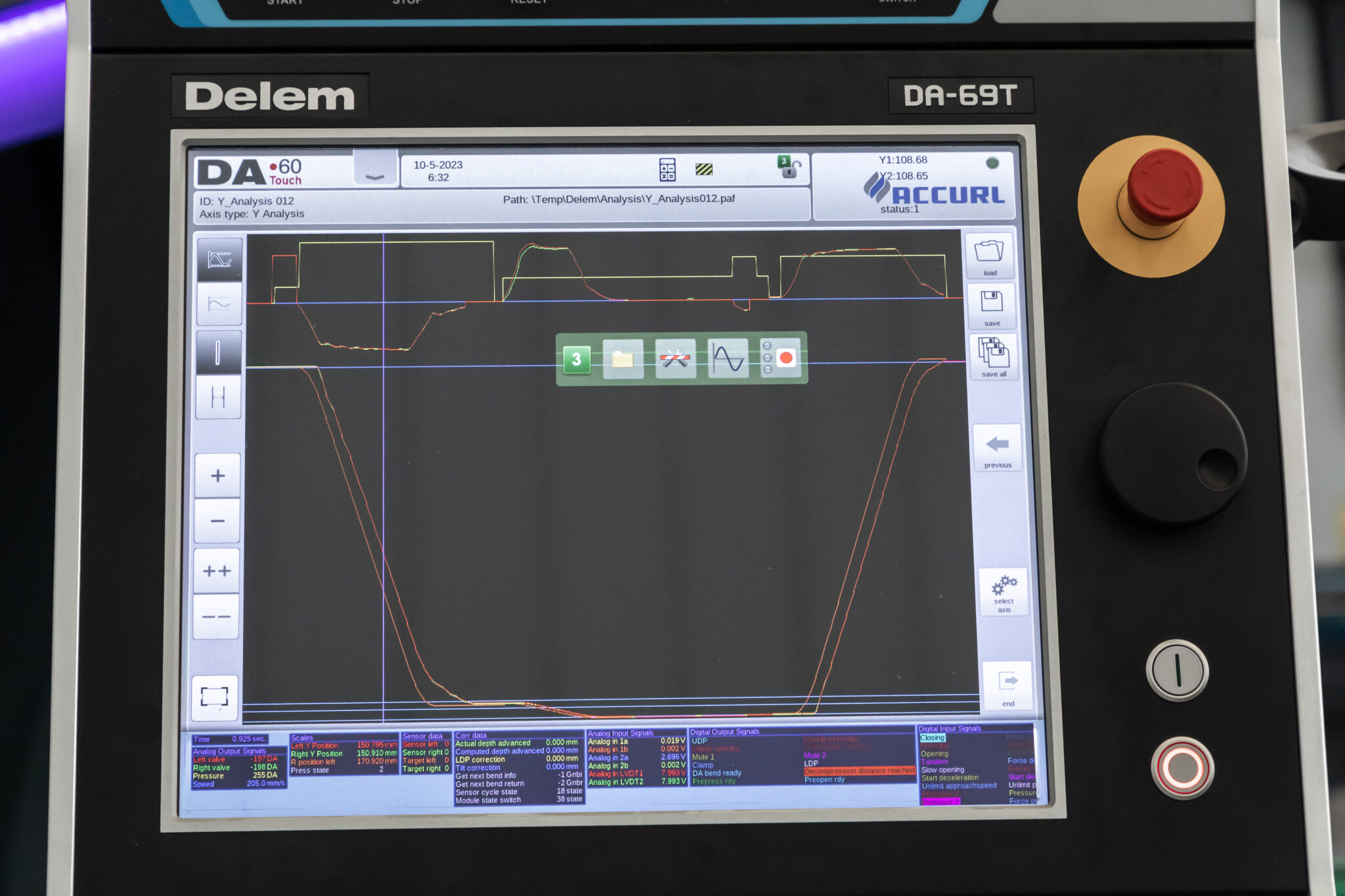
Many operators overlook the importance of keeping firmware up to date, yet it plays a central role in how the control system interprets commands, processes sensor feedback, and manages safety protocols.
If your system hasn’t been patched in a while, you might experience angle repeatability errors after updates, especially during air bending or complex bend sequencing. This often means the CNC parameters were reset or corrupted. Reconfiguring these parameters restores system precision and ensures proper coordination with devices like the back gauge, filling valve, or pressure control valve.
Unexpected software behavior, like a delay in descent, skipped menu options, or mismatched punch/die configurations, can be traced to internal control bugs. You should also tighten all relay and terminal connections quarterly, as loose leads may trigger sudden machine stops or false alarms.
Firmware compatibility also affects how the system enforces safety zones, monitors the ram’s movement, and responds to overloads or material-related stress concentration. Outdated logic may ignore updated tooling dimensions or ignore critical values like oil level, slider speed, or bend angle limits, leading to dangerous outcomes.
What Operator Mistakes Can Compromise Quality and Safety during Press Brake Use?
Even the most advanced press brake machine can fail if the operator overlooks critical steps. Mistakes made during setup or operation don’t just affect the bend angle or final shape, they can reduce service life, damage components, or put safety at risk. As you manage equipment, it’s essential to understand how small oversights can escalate into production-wide failures.
Skipping Pre-work Safety and Setup Checks
Every shift should begin with a safety checklist. Skipping this step exposes you to multiple hazards and equipment damage. You need to confirm oil level, inspect for oil leaks, and verify tooling alignment. Failure to identify clearance issues or guide rail wear may result in inconsistent force distribution or slider movement errors during the bending process.
Neglecting to check the pressure control valve, back gauge, and filling valve can lead to sudden descent or delayed return stroke, particularly during air bending.
A buildup of dust on sensor components or failure to clean tooling surfaces properly can trigger inaccurate feedback to the control system. If unchecked, these factors reduce accuracy, waste material, and introduce unwanted stress concentration on both the workpiece and the die..
Misreading Work Instructions or Drawings
Operators who rush through setup without fully reviewing technical drawings often introduce critical bending problems. Misinterpreting the bend radius or material thickness can cause incorrect tool selection, unexpected flange width, or deflection in the bed. These errors might not be immediately obvious but compound over time, affecting overall product quality.
You should always double-check all parameters, tooling dimensions, angle tolerances, and material placement instructions, against the digital readout or printed sheet. Press brake machines depend on precision.
When you enter incorrect input into the system or overlook the shape requirements of a punch or workpiece, you’re more likely to exceed design limits, causing damage to parts or creating dangerous load conditions. This is especially important when working with varied metals or unfamiliar components.
Bending Parts the Wrong Direction
When you bend a part the wrong way, the error is rarely recoverable. This often occurs when there’s confusion about the material’s orientation or surface finish. In press brake operations, direction matters, especially when the design calls for specific bend radius or flange width.
For example, if you ignore material placement instructions or rotate the workpiece incorrectly, the final bend angle will be misaligned with the intended form. That mismatch introduces stress concentration at critical points, weakening the part’s structure. The tooling setup might still be correct, but the visual directionality of the material influences final product shape.
You should always reference the drawing’s directional cues and double-check during loading..
Using Incorrect Machine Settings
The pressure required for each bend varies based on material thickness, bend radius, and tooling configuration. If you fail to calculate the correct bending load, you risk overloading the hydraulic cylinder, damaging the machine, or even causing operator injury.
Modern press brake machines come with tonnage charts for a reason. These help you match material type, length, and bend angle to appropriate force levels. When you skip this step or use default settings, it often leads to tooling damage, excessive deflection in the bed, or inconsistent results. This is especially critical in air bending, where tonnage and ram movement precision dictate final part geometry.
Speed settings, return pressure, and stroke limits must all be configured correctly to match the specific bend process and tooling used.
Fatigue and Repetition Errors
When you work long shifts with repetitive tasks, your attention to detail can drop. This is when you’re most likely to misread instructions, skip pre-bend checks, or miscalculate bend sequence. Fatigue also raises the likelihood of overlooking oil leakage, friction buildup, or valve irregularities.
To prevent this, schedule short breaks and rotate operator positions where possible. Remind yourself to visually inspect each workpiece before pressing ‘Start.’
Establishing a first-article inspection process, especially after tooling changes or shift handovers, reduces scrap rates and maintains quality. If you’re consistently producing more than 3% scrap, it’s often due to rushed setup or skipped calibration checks.
Excess repetition without breaks can dull your response to error messages or audible alarms from the control system. Small delays in reaction may seem minor but can lead to longer-term damage in hydraulic systems or equipment alignment.
What Maintenance Oversights Lead to Press Brake Failures?
When you overlook scheduled upkeep, press brake failures become more likely. These breakdowns don’t just stop your operation; they often damage key components like the hydraulic system, ram, or back gauge, leading to expensive downtime and lost efficiency.
Most issues stem from small, preventable causes—things you might overlook during day-to-day operation.
Consistent press brake maintenance helps reduce oil leaks, deflection in the bed, irregular slider movement, and even failures in the pressure control valve. When these elements degrade, the entire bending process suffers. Over time, neglect leads to imprecise bend angles, tooling misalignment, or problems with material placement that result in scrap or rejected parts.
For a deeper look at prevention strategies, check this resource on press brake maintenance. It includes practical checklists to help you avoid common causes of failure.
Not Cleaning the Machine Regularly
Dust and metal particles accumulate quickly on a sheet metal machine. If you don’t clean the press brake frequently, dirt clogs the guide rail, affects sensor readings, and adds friction to critical components. This buildup also accelerates wear on the tooling surfaces and hydraulic cylinders.
A dirty machine increases the risk of inaccurate feedback in the control system. Dirt can interfere with oil level readings, lead to filling valve blockage, or cause premature damage to fixtures and tooling.
Cleaning should extend beyond visual surfaces, it includes sensors, bed plates, and underneath the punch or die components. Small particles affect how precisely the machine responds during bending.
Ignoring Lubrication Schedules
Lubrication is essential to reduce friction and heat buildup. When you skip scheduled lubrication, moving parts grind down faster. This increases stress concentration along the guide rail and bearings, shortening your press brake machine’s service life.
Lack of lubrication also leads to inconsistent return stroke performance and irregular descent speeds. The control system might still run, but hydraulic oil won’t circulate efficiently without proper lubrication. This weakens system pressure, especially during tonnage peaks in air bending operations.
Stick to the lubrication instructions recommended by your equipment provider. Regular lubrication maintains the mechanical clearance needed between contact elements.
Failure to Replace or Adjust Oil
The hydraulic system inside your press brake depends on clean, properly filled oil. Over time, hydraulic oil degrades, and contaminants increase. This affects the pressure control valve, return pressure behavior, and filling valve responsiveness. If you’re not checking the oil level or replacing the oil according to schedule, you’re putting the entire bending process at risk.
Dirty oil creates internal leakage and reduces the efficiency of movement in the ram and cylinders. You may also notice noise increases, a delay in return stroke, or erratic movement. These are early signals of system strain. Oil that’s too thick or too low causes the hydraulic cylinder to overheat and lose precision during tonnage-intensive processes like air bending.
Don’t wait for error messages or part defects. Make oil analysis a standard maintenance procedure, especially if your machine runs multiple shifts.
Skipping Periodic Alignment Checks
Just like a car’s tires, press brake components shift over time. Heat, pressure, and vibration gradually alter the alignment between the punch, die, and work bed. When tooling alignment is off, you’ll see inconsistent flange width, incorrect bend radius, and increased tool chipping. These bending problems aren’t isolated—they affect every product that passes through the machine.
Skipping alignment checks also accelerates wear in the guide rail and bed. When gib alignment is ignored, friction increases across contact surfaces. Improper lubrication on top of misalignment can double the wear rate in less than 12 months, especially under high-load conditions.
Even a 0.1 mm shift in alignment can cause dimensional tolerance issues across a full production batch. That’s why alignment should be checked routinely—not only after tool changes or machine relocation. If your checklist doesn’t already include alignment verification, it’s time to add it.
What Preventative Practices Improve Safety and Reliability While Using Press Brakes?
Practices such as checking oil level, inspecting the cooling system, and adjusting the slider for tooling alignment should become second nature. This doesn’t just protect equipment—it ensures material placement, bend angle accuracy, and reduces stress concentration on the bed and ram.
Routine Preventive Maintenance Checklist
Establishing a structured maintenance checklist helps reduce damage and friction-related wear:
- Daily cleaning of tooling surfaces and die bed: Dirt buildup increases deflection and interferes with accurate material support.
- Weekly oil leakage inspections: Spotting oil leaks early helps prevent pressure fluctuations that harm the filling valve or hydraulic cylinder.
- Tooling alignment checks every 40 hours of use: Misalignment leads to uneven flange width and forces that exceed allowable tolerances.
- Back gauge calibration monthly: Even slight deviations in position can ruin product dimensions and bend radius.
- Lubrication of wear points as scheduled: Missing intervals increases the rate of wear on the guide rail and increases return pressure inconsistencies.
Avoiding Force Concentration
Press brakes operate under intense tonnage. When the load isn’t evenly distributed across the workpiece, you get force concentration, one of the primary causes of early component wear and fixture damage. Misplaced bends, incorrect die width, or poor material thickness matching can all create localized pressure spikes. These spikes damage parts, crack punch tips, and reduce tooling life.
To avoid this, you should:
- Match die opening and punch radius to material type and thickness
- Use material support brackets for long workpieces to prevent downward force shifts
- Monitor bend angle changes across the sheet to detect uneven force application
Never Bypassing Safety Systems
You should never disable or bypass any built-in safety system. Press brake machines are equipped with features that protect both the operator and the workpiece. These include light curtains, ram descent monitoring, and emergency stop functions integrated into the control system.
When bypassed, these systems can’t detect slider anomalies, return stroke irregularities, or deflection beyond allowed tolerances.
By relying on all intended safety checks, you reduce risks tied to friction buildup, force misdirection, and die misalignment. It also prevents damage from unexpected workpiece movement or failed sensor readings. Tooling surfaces and components remain intact longer, and error messages triggered by anomalies can guide you to early-stage problems.
Implementing a Digital Log or Maintenance Management System (CMMS)
To reduce unplanned failures, you need visibility into how your equipment performs over time. This is where a CMMS becomes a game-changer.
By tracking error messages, hydraulic oil temperature, wear cycles, and valve behavior, you’re no longer reacting to problems, you’re preventing them.
Modern CMMS software integrates with advanced control systems, helping you schedule checks for oil level, slider friction, or back gauge drift. CMMS users have been shown to reduce emergency repairs by 30%, which translates to fewer interruptions in the bending process and greater production consistency.
Here’s what a digital log can help you track and control:
- Hydraulic system health: Detect early signs of oil leakage, return pressure imbalance, or pressure drops in the filling valve or pressure control valve.
- Tooling condition: Schedule inspections of punch surfaces and dies to avoid chipping, cracks, and tolerance drift.
- Cooling system and lubrication routines: Ensure proper oil temperature regulation and slider movement with timely lubrication.
- Machine behavior trends: Analyze causes of bend angle inconsistency or stress concentration in fixtures and bed areas.
What Role Does Automation and CNC Programming Play in Reducing Mistakes in Press Brake?
Manual machines often rely on the operator’s experience, increasing the risk of inconsistent bend angles, flange width deviation, and stress concentration at critical points. Even minor inconsistencies in material thickness or positioning can result in costly bending problems or part rework.
Automation helps eliminate many of these variables. CNC press brakes integrate advanced control systems that manage ram movement, back gauge positioning, and bend radius with higher accuracy.
Automated angle-measurement systems feed back corrections within 0.2 seconds, helping you maintain bend angle tolerances within ±0.5°, even during high-speed operations.
Beyond accuracy, CNC programming minimizes setup errors. Programmed parameters ensure the slider, tooling alignment, and descent speed follow exact instructions.
By verifying part geometry, bend sequence, and clearance ahead of time, you reduce operator errors that often arise from manual judgment.
Offline program simulation takes it further. You can simulate tool paths before cutting any workpiece. This prevents collision risks, especially with large dies or unconventional shapes, and saves around two hours per setup changeover. When you’re managing a bending machine fleet, that time adds up fast.
Still, even CNC systems depend on correct inputs. Poor programming or skipped checks can cause tool chipping, missed return strokes, or oil leakage under unexpected loads.
That’s why it’s essential to test programs before going live, your tooling surfaces and production schedule depend on it.
What Should Be Included in a Troubleshooting Press Brake Checklist?
When performance drops or parts begin to show defects, you need a structured way to identify root causes. A troubleshooting checklist gives you that structure, helping you diagnose bending problems based on symptoms you can see, feel, or hear during operation.
The table below serves as a quick reference to guide your inspection. Whether you’re addressing oil leaks, faulty valve behavior, or bend angle inconsistencies, this chart connects real symptoms to the systems involved, so you can act faster and more accurately.
| Problem or Symptom | Likely Cause(s) | Area to Inspect or Maintain | Suggested Resolution |
|---|---|---|---|
| Inconsistent bend angle | Tooling wear, material thickness variation | Tooling surfaces, material specs | Replace worn punches/dies, verify material specs |
| Back gauge misalignment | Guide rail shift, calibration drift | Back gauge, control system | Recalibrate gauge and secure guide rail |
| Oil leakage around cylinder or valve | Seal wear, pressure control valve failure | Hydraulic system, filling valve | Replace seals, inspect pressure valve and oil level |
| Ram movement delay | Return pressure imbalance, contamination | Hydraulic cylinder, oil filter | Clean filters, check return stroke pressure |
| Workpiece slipping or poor placement | Incorrect material support or dirt | Material support, bed | Clean bed area, verify fixture setup |
| Program not executing properly | Coding error, software bug | CNC system, program menu | Debug CNC file, re-upload verified simulation |
| Excessive noise during operation | Tooling misalignment, die damage | Punch and die set | Realign tooling, inspect for cracks |
| Angle out of tolerance | Air bending error, springback issues | Process type, tooling radius | Use angle correction system, modify bend radius |
| Frequent emergency stops | Operator errors, faulty safety circuit | Safety interlocks, descent sensor | Train staff, inspect sensor response times |
| Poor edge quality | Incorrect bend parameters | Control panel, machine settings | Adjust speed, pressure, bend direction |
| Oil temperature rising too fast | Cooling system failure | Cooling unit, oil circuit | Service cooler, check for blockages |
| Programmed angle not matching output | Poor calibration or missed update | CNC parameters, angle sensors | Recalibrate sensors, review last update |
| Slider gets stuck mid-process | Friction, lack of lubrication | Slider rail, lubrication system | Clean and lubricate rail, inspect movement path |
| Frequent tool chipping | Force overload, incorrect punch selection | Tooling specs, tonnage setting | Adjust tonnage, choose correct punch for thickness |
| Bends vary with same program | Material variation | Sheet metal consistency | Sort materials, adjust process for known tolerances |
| Hydraulic pressure drop | Leak, worn pump | Pump, valves, hose connections | Replace pump, tighten connections |
| Control panel freezing | Software glitch, electrical issue | Electrical circuits, program memory | Restart system, check all circuit connections |
| Return stroke too slow | Return pressure low | Hydraulic pressure settings | Recheck pressure setting, refill hydraulic oil |
| Material colliding with machine | Program path error | Offline simulation, fixture setup | Run simulation, modify material placement strategy |
| Dust buildup around moving parts | Lack of cleaning routine | Machine frame, guide rail | Schedule regular cleaning procedure |
How Often Should I Calibrate My Press Brake?
If your angles start drifting or you notice inconsistencies in material thickness response, that’s often the first sign your calibration is overdue. For full mechanical calibration, leading OEMs recommend doing it every 12 months or every 250,000 cycles, whichever comes first.
You should also verify angle sensors and back gauge axes quarterly. This helps maintain force control, slider movement consistency, and precision in automated bending machines. A proactive schedule like this reduces tooling wear, catches filling valve lag early, and helps prevent damage across the hydraulic system before it impacts your operation.
Conclusion
Your press brake does a lot more than just bend metal. It’s a complex machine that runs on precision, timing, and care. From the hydraulic system and control circuits down to the punch and back gauge, every part plays a role.
If one thing slips, like oil level, tooling alignment, or sensor calibration, it can throw everything off. That’s why having a solid troubleshooting checklist isn’t just helpful. It’s essential.
But here’s the thing: we’re not just trying to stop problems. We’re trying to understand them. You need to know why that bend angle is off or where that oil leak is coming from, because when you get ahead of the issue, you’re protecting more than parts. You’re saving time, money, and stress.
We’ve all been there, rushing a job, skipping a check, and hoping for the best. But in this game, prevention always beats repair.
When you know what to look for, you keep your press brake running smoother, your parts looking cleaner, and your production moving without a hitch. It’s not about perfection. It’s about control. And the more you understand your machine, the more control you’ve got.


