Press brakes are found in most metalworking workshops. Press brakes are crucial equipment for many industries, from small household furniture to large aircraft. This article will explain what is a press brake and go into the details of how it works.
What is a Press Brake?
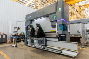
Press brake is a metal bending machine. It is used in industries and fabrication shops for bending sheet metal to a desired angle and shape. The sheet metal bending process is accomplished by applying force on the point of the bend.
Press brakes can bend metal sheets and metal plates. The degree of the bend is called bend angle. Industrial press brakes are usually automated and controlled with a CNC machine.
When Was Press Brake Invented?
Press brakes were first patented in 1882. Since there were no automated systems then, early press brakes relied on a lot of manual labor. First, a mold was made in the shape of the required part. Then the sheet metal was placed on the mold. The mold was filled with sand and lead shots. The human labor would pound on the sheet metal with a T-stake until the bend formed. The bends with this method were in a straight line.
How Does a Press Brake Machine Work?
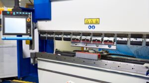
Press brakes rely upon two tools- the punch and die. Die is a tool placed under the workpiece. It is usually in a V-shape. The punch is a movable component over the workpiece. It applies force on the workpiece to bend it. The punch is typically long with a narrow width.
A ram drives the movement of the punch. There are multiple options for the ram movement, such as mechanical, servo motors, hydraulic, and pneumatic. The entire setup is housed on the workbench.
Some terms to remember while working with press brakes are:
- Tonnage: Tonnage refers to the bending force of the particular press brake. Tonnage determines the press brake’s load limit. If a press brake has a higher tonnage, it can bend thicker and longer sheet metal.
- Bending Angle: The bending angle is the angle between the two sides of the bend.
- Bending Length: The bending length is the maximum length limit of the sheet metal that you can bend with a particular press brake.
What are the Different Types of Press Brakes?
There are four different types of press brakes based on their working processes. These types are:
Mechanical Press Brakes
Mechanical press brakes have a flywheel mechanism to drive the up-and-down movement of the punch. The flywheel controls the gear shaft with a clutch system.
A mechanical brake press has a very simple setup. This makes them easy to operate for any workshop. If something breaks down, the components are easily repairable and replaceable. They are also flexible and can lift a higher tonnage than what is rated on the machine.
However, a mechanical press brake provides poor control over the punch speed. The quality and accuracy of the bends are also poor.
Hydraulic Press Brakes
A hydraulic press brake uses two oil cylinders to control the punch instead of the mechanical clutch setup. Hydraulic press brakes are a significant upgrade from the mechanical alternative. Due to the hydraulic system, these press brakes have far superior bending capabilities than mechanical press brakes. The bending accuracy of hydraulic presses is also higher.
However, hydraulic press brakes have complex parts and setups. A more skilled operator is required to operate these brake presses. A hydraulic press brake incurs high repair costs in case of a component breakdown. Additionally, these machines require strict adherence to rated tonnage. Going higher than the rated values will break down the machine. There is also the risk of fluid leakage in the hydraulic cylinders.
CNC hydraulic press brakes have become one of the most popular options in modern usage. This type of press brake has an automated system to control the machine’s movement and timing.
Pneumatic Press Brakes
Pneumatic press brakes are similar to hydraulic brakes. A pneumatic press brake uses air pressure to move the punches and dies. Air is filled into a tube which then applies pressure to the press brake punch. Once the bending is completed, the air is pumped out from the tube. The punch then moves up again.
Air pressure is easier to control than water. Therefore, pneumatic press brakes have a significantly higher working speed than hydraulic press brake. It is also easy to halt the operation midway.
However, the power of pneumatic press brakes is quite lower than that of a hydraulic press brake. Therefore, pneumatic press brakes are less applied in heavy-duty applications than their pneumatic counterpart.
Servo Press Brakes
Servo press brakes move the punch with a pair of servo motors. These are also known as servo-electric press brakes or simply electric press brake. The mechanical power generated by a servo motor is transferred to the punch with a system of pulleys and belts.
Servo motors come with a lot of minute adjustment options. This provides a greater degree of control over the punch movement. The bends created with a servo press brake are very precise. Additionally, an electric press brake has a noiseless operation leading to a quieter workplace. Servo brakes eliminate the problem of leakage since there are no oil or air cylinders.
However, the force generated by a servo press brake is very low compared to other alternatives. Therefore, these press brakes do not find a lot of application in industrial uses that have a higher tonnage.
CNC Press Brake
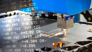
A CNC press brake is a versatile and automated machine that operates through a computer numerical control system (CNC), allowing for precise and repeatable results. With a CNC press brake, businesses can increase their productivity, efficiency, and accuracy while reducing their overall labor costs. CNC press brakes are ideal for a wide range of applications and industries, from aerospace and automotive to construction and electronics.
What are the Benefits of Press Brakes?
There are many advantages of using press brake machines in your workshop. These advantages are:
In-house Setup
A press brake is a relatively cheap and easy-to-use industrial equipment. Manufacturers can install a press brake machine in their own facility instead of outsourcing the process. This saves up manufacturing costs and production time for a business.
Safeguards
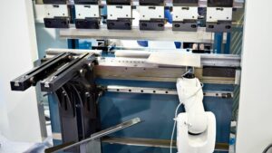
A modern press brake has multiple safeguards in place to ensure operator safety. There is a curtain safety device on the sides, so the operator’s arms and hands are away from harm’s way. There are also laser sensors to avoid possible accidents in the workplace.
Fast Production
Integrating Computer Numerical Control (CNC) in a press brake is common. This makes the entire operation of the press brake automated. Therefore, manufacturers can have a faster production setup by using CNC press brakes.
Reduced Physical Effort
Press brakes reduce the need for physical labor. The automated setup means that operators only have to oversee the operation and intervene solely for loading and unloading.
Reduced Costs
Due to faster production and lesser labor requirement, the entire operation costs are reduced. This also reduces the per-unit cost of the manufactured parts.
What are the Applications of Press Brakes?
Press brake finds application in all segments of the manufacturing sector. Some common products made using a press brake are:
- Machine Tools: A press brake makes parts for other machine tools. This includes the machine enclosures, tanks, frames, and other components.
- Electrical Parts: Electrical parts such as junction boxes and enclosures are made with press brakes.
- Automotive Industry: Press brake is used in the automotive sector for fabricating frame components.
- Construction: Press brakes make frames and duct parts for the architecture and construction industries.
Are There Any Limitations of a Press Brake?
Press brakes are really good at what they do. Some manufacturers can see certain aspects of a press brake as a drawback. These potential drawbacks are:
- Incorrect press brake use and inappropriate pressure can lock the ram.
- Most press brakes do not halt midway. Once the operation starts, the ram will require completing the cycle of going down and up. This can be troublesome if the operator makes an error and wants to stop the operation.
Is There Any Alternative to a Press Brake?
Press brakes have high functionality and are irreplaceable in the modern manufacturing industry. However, some of the operations of a press brake can be achieved with alternatives like:
Folding Machines
In folding machines, the workpiece extends forward from a back gauge table. The bending die applies pressure on the extended part to create the bend. Folding machines are more complex than press brakes and have a slower production rate.
Panel Benders
Panel benders are alternatives of a press brake for very thin metal sheet. A panel bender is significantly more expensive than a press brake.
Conclusion
Press brakes are a must-have in any metalworking facility. You will see a press brake in every fabrication workshop, whether small or large. Accurl provides a range of modern electric & hydraulic press brakes with industry-leading specifications and competitive pricing. Get in touch with Accurl to find the right machine for you.